Motor protection systemmotor protection control and management. It reveals the parts of the circuit as streamlined shapes and the power as well as signal links in between the gadgets.
 Rtd Wiring Diagram Wiring Diagram 500
 The 869 motor protection system description acceleration time phase reversal broken rotor bar reduced voltage starting rtd temperature motor.

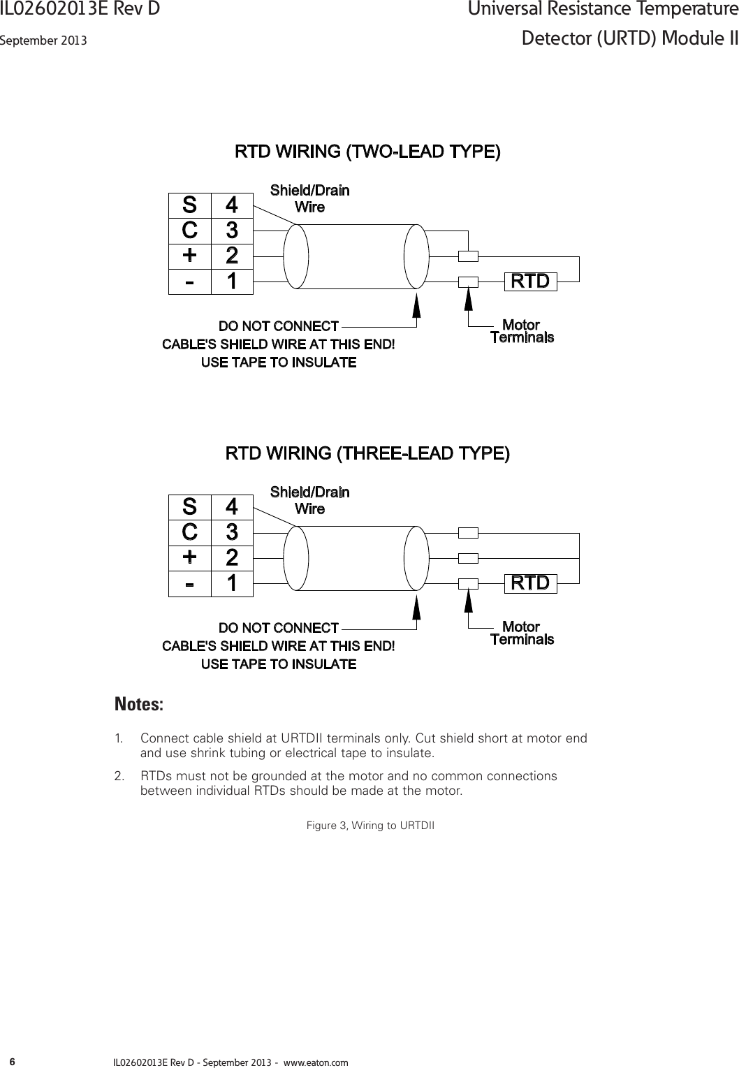
Motor rtd wiring diagram. Each type of rtd has its own particular resistance characteristic. Most rtd termination boxes are large enough to accommodate the rtd module. Mercury trim motor wiring diagram download collections of mercruiser trim solenoid wiring diagram yahoo image search results.
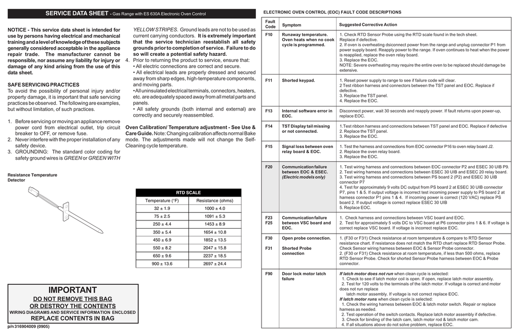
B the rtd module goes in series with the existing rtd wiring. The rtds used in motor windings are either 10 ohm 100 ohm or 120 ohm. The rtd module is 7 inches long and 175 inches wide and 1 inch high.
Motor rtd wiring diagram collection 3 wire pt100 connection diagram 3 wire rtd connection to plc. Temperature transmitter circuit diagram fresh rtd circuit diagram. Galericanna wp content 2018 07 mercury.
L1 and l3 carry the measuring current while l2 acts only as a potential lead. The basic detectors are listed below. A verify if the existing rtd termination box at the motor frame is large enough to install the rtd module.
The rtds are installed in the slot portion of form wound motors and either in the slot standard or in the end turns of mush wound motors. 4 wire rtd signal connection connect each of the red leads on the positive side of the resistive element to the excitation positive and channel positive on the daq device. It shows the way the electrical wires are interconnected and may also show where fixtures and components could possibly be coupled to the system.
Thermocouple wiring diagram new cool rtd wire color chart ideas. A wiring diagram is an easy visual representation from the physical connections and physical layout associated with an electrical system or circuit. Rtd sensor temperature ppt video online.
In this circuit there are three leads coming from the rtd instead of two. A wiring diagram is a simplified traditional pictorial representation of an electrical circuit. No current flows through it while the bridge is in balancesince l1 and l3 are in separate arms of the bridgeresistance is canceled.
Assortment of rtd pt100 3 wire wiring diagram. Typical wiring diagram contactor application with open transition wye. Tilt and trim switch wiring diagram awesome technical information.
It shows the components of the circuit as streamlined shapes and also the power and also signal links between the gadgets. View and download ge mi 869 instruction manual online. 3 wire rtd wiring diagram.
Assortment of motor rtd wiring diagram. The following connection diagrams illustrate how to connect various rtd types to your daq device. Motor rtd wiring diagram what is a wiring diagram.
Tilt and trim switch wiring diagram best trim and hydraulics need. A wiring diagram is a streamlined standard photographic depiction of an electrical circuit.
 Diagrama De Cableado En Ingles Espanol Y Frances Manualzz Com
  Wiring Diagram
  Wiring Diagram Manualzz Com
  Product Detail Manual
  Rtd Construction And Lead Wire Configurations Learning
  A2f Dishwasher Pump Motor Wiring Diagram Wiring Resources
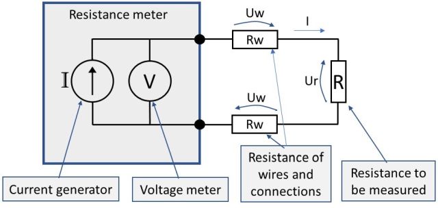
  Resistance Measurement 2 3 Or 4 Wire Connection How Does
  3 Wire Electric Diagram Wiring Diagram Rows
 .jpg) Principle Of Operation Of A Resistance Temperature Detector
Principle Of Operation Of A Resistance Temperature Detector